MCC (Motor Control Center) bucket is an essential component, which houses the controls, as well as protection devices for individual motors in industrial applications. This article reviews what an MCC bucket is, its components, a typical wiring diagram, and also a size chart.
What is an MCC Bucket?
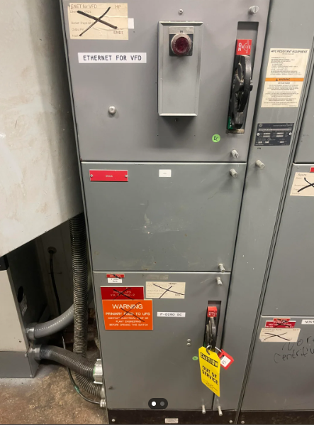
It is easy to confuse the term “MCC Bucket” with “MCC enclosure,” so let’s clarify their differences. An MCC enclosure is a centralized structure with various compartments designed to hold MCC buckets. Furthermore, these MCC buckets are assigned to individual motors or specific loads. In contrast, an MCC bucket is a compact, modular unit that contains individual motor control components. For example, circuit breakers, starters, contactors, panel boards, fusible disconnect switches, relays, fuses, or variable frequency drives (VFDs).
Generally, a bucket is installed with a screw mechanism between the surface of the compartment and the bucket foundation panel. On the front side, the bucket contains an opening door for easy access as well as a manual on-off switch.
An MCC bucket mainly provides localized control of motors in electrical power distribution networks, equipment, factories, and also other application areas. In addition, it facilitates easy maintenance and replacement, and usually work alongside PLCs.
MCC Bucket Components
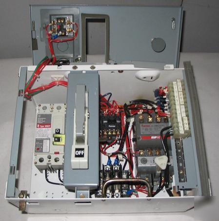
An MCC bucket involves various components to control and regulate an individual motor or a specific section of the motor load. The components will vary according to the function and type of the MCC but typically include motor starters, fuses, and transformers.
Motor Starter
The electric motor starter is the central component that facilitates the straightforward way of turning on and off the motor. The motor starter controls this through the electrical power supply. A shaft wiring or core starter is suitable for simple motor control systems, whereas VDFs are necessary for complex and large networks.
Circuit breaker
The circuit breaker opens itself to break the motor circuit during faulty situations, such as over-current, short circuit, and ground faults. Typically, thermal-magnetic or electronic circuit breakers are used in the MCC bucket. The following sections highlight a few of these key components.
Overload Relay
The overload relay detects the excessive current (overload) and deactivates the contactor to avoid heat build-up and further damage. Thus, minimizing equipment downtime. Both thermal and electronic relays are popular for overload protection.
Current and Voltage Transformer
Typically, a voltage transfer is used to step down the supply voltage within the desired operational range. These components are essential to maintain the functionality and also variables of the motor.
Switch and Indicators
The front door of these metal enclosures usually consists of a starter switch, light indicators, as well as push buttons attached to it. They facilitate the easy operation and inspection of MCC buckets.
Terminal Block
A terminal block provides connection points for the motor leads and also incoming power. Thus, facilitating easy and accessible wiring connections between the bucket and the motor.
MCC Bucket Wiring Diagram
The components mentioned above are wired in a systematic approach to ensure functionality and avoid damage.
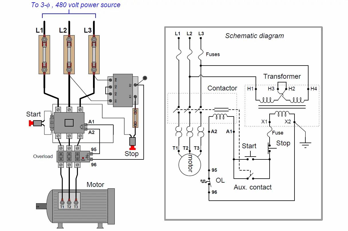
The diagram above shows the power circuit, as well as the control circuits of an MCC bucket. A three-phase supply (L1, L2, L3) is connected to the main switch and the motor starter. Each phase further connects with the overload protection and also the circuit breakers. Then, the supply goes to the motor connectors (T1, T2, T3).
Generally, the start and stop buttons control the motor by energizing or de-energizing the contactor coil (A1, A2), which closes or opens the main power contacts. The overload relay’s auxiliary contacts (95, 96) monitor for overloads. When this is detected, it opens and stops the motor by cutting power to the contactor coil.
Steps in MCC Bucket Wiring
- Connect the MCC bucket to the three-phase busbar power supply and also ensure a secure connection to the main disconnect or circuit breaker.
- Next, connect the motor to the load side of the contactor or starter.
- Wire the control devices to the control circuit terminals, such as start/stop buttons, indicator lights, as well as overload relays.
- Then, connect the control circuit to the motor starter coil.
- Finally, connect all metallic components to the grounding busbar and test the MCC.
Motor Control Center Bucket Size Chart
Both manufacturers and industry regulators utilize an MCC bucket size chart to provide details about the different sizes of buckets. These charts are essential for engineers and also technicians to appropriately select bucket sizes in line with motor control needs. Key details that are usually on these charts include the following:
- Bucket Sizes: Different standard sizes according to the manufacturer or regulator, for example, NEMA sizes (00, 0, 1, 2).
- Dimensions: Height, width, and depth of each bucket size.
- Power Ratings: Maximum current and voltage ratings.
- Component Capacity: Types and quantities of components (e.g., circuit breakers, starters, contactors) each bucket can house.
- Compatibility: Information on what type of MCC enclosures or systems the bucket sizes are compatible with.
- Additional Features: Options for additional features like metering, control wiring, or special protection devices.
The following chart is an example from NEMA.
| NEMA Size | Current Rating (Amperes) | 200V 60 Hz | 230V 60 Hz | 380V 50 Hz | 460V 60 Hz | ||||
| Hp | LRA | Hp | LRA | Hp | LRA | Hp | LRA | ||
| 00 | 9 | 1.5 | 46 | 1.5 | 40 | 1.5 | 30 | 2 | 25 |
| 0 | 18 | 3 | 74 | 3 | 70 | 5 | 64 | 5 | 53 |
| 1 | 27 | 7.5 | 151 | 7.5 | 140 | 10 | 107 | 10 | 88 |
| 2 | 45 | 10 | 255 | 15 | 255 | 15 | 255 | 25 | 210 |
| 3 | 90 | 25 | 500 | 30 | 500 | 50 | 500 | 50 | 418 |
| 4 | 135 | 40 | 835 | 50 | 835 | 75 | 835 | 100 | 835 |
| 5 | 270 | 75 | 1670 | 100 | 1670 | 150 | 1670 | 200 | 1670 |
| 6 | 540 | 150 | 3340 | 200 | 3340 | 300 | 3340 | 400 | 3340 |
| 7 | 810 | – | – | 300 | 5000 | 300 | 5000 | 600 | 5000 |
| 8 | 1215 | – | – | 450 | 7500 | – | – | 900 | 7500 |