Busbar protection is crucial for ensuring the safety and reliability of electrical power systems. This article reviews what busbar protection is, as well as compares the features of low impedance vs high impedance protection.
What is Busbar Protection
A busbar is a metal strip or a series of metal strips connected together, facilitating the smooth connections for incoming and outgoing feeders. You can also refer to it as a junction point where electrical currents converge and distribute to the loads or switchboards. Meanwhile, the busbar protection ensures the safety and reliability of the busbar by monitoring and detecting possible faults like overcurrent, short-circuit, and earthing failures. It isolates the affected section using connected circuit breakers when faults are detected.
The typical components of a busbar protection device are as follows;
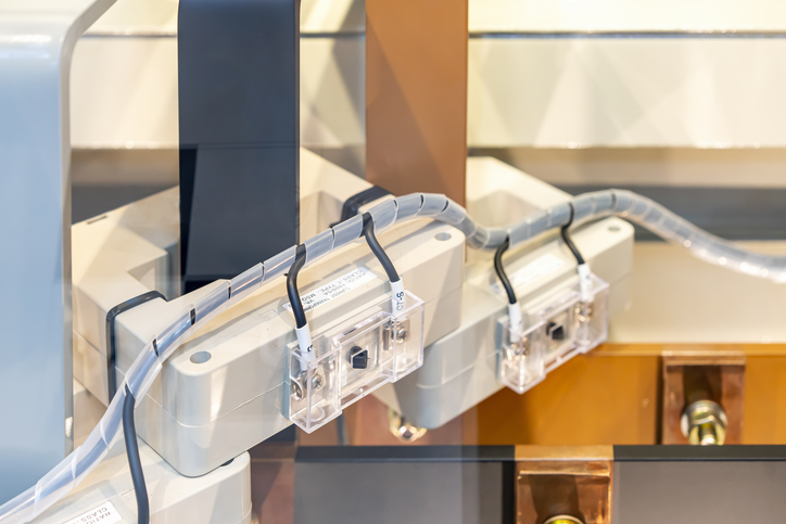
- Current Transformers (CTs): CTs measure the current at both ends or specific busbar sections and send the singles to protection relays.
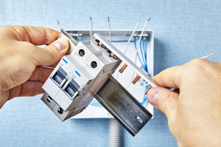
- Relays: They receive the currents from CTs and compare them with the pre-programmed criteria. If it exceeds or does not match the specifications, then corresponding circuit breakers deactivate connection via trip signals.
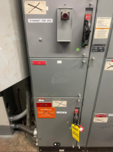
- Control panel: It provides the user interface to monitor the status and program the relays. The relays can be reset for regular tasks after responding to the fault notifications with accurate maintenance.
Moreover, various busbar protection schemes like low impedance and high-impedance busbar protection systems exist. These differential protection schemes provide higher sensitivity, even for minor internal faults.
Low Impedance Busbar Protection
Low impedance busbar protection is a type of differential protection scheme. Its design allows it to detect faults by comparing the sum of currents entering the busbar with the sum of currents leaving the busbar. Thus, working on the basis of Kirchhoff’s Current Law (KCL). The term “low impedance” stems from the low value of the stabilizing impedance that the relay uses to achieve fast and sensitive fault detection.
How Low Impedance Busbar Protection Works
- Differential Protection: The scheme operates based on the principle of KCL. This law states that the sum of currents entering a node must equal the sum of currents leaving the node in the absence of faults.
- CTs and Summation: Current transformers (CTs) are installed on all lines connected to the busbar. The secondary currents of these CTs are summed, and any imbalance indicates a fault within the busbar zone.
- Low Impedance Relay: The protection relay has a low impedance setting to detect even minor differences between the summed currents, ensuring high sensitivity.
On the basis of this working principle, the low impedance busbar protection could either operate in its normal conditions, have an internal fault, or an external fault.
- Normal Condition: Under normal operating conditions, the sum of currents entering and leaving the busbar is zero, and the differential relay does not operate.
- Internal Fault: If a fault occurs within the busbar zone, the current balance is disturbed, creating a differential current that exceeds the relay’s set threshold. The relay then issues a trip signal to isolate the faulted section.
- External Fault: During an external fault, the current balance remains, and the relay remains stable, not issuing a trip signal.
Advantages
- Quick Response: The low impedance busbar protection quickly detects the fault and isolates the circuit, typically in a few milliseconds.
- Simple setup: The programming and setup are simple; only the restraint current value must be set for reference.
- High Fault Currents: The large current fault (a large difference from the reference value) is detectable as low impedance facilitates the measure of higher current levels.
- High Sensitivity: The low impedance setting allows the detection of even low-level faults that might not be detected by other protection schemes.
- Stability During External Faults: The scheme is stable during external faults. Thus, it does not operate incorrectly for faults occurring outside the protected busbar zone.
Disadvantages
- CT Saturation: Accurate operation requires that CTs do not saturate during high fault currents. Saturation can lead to incorrect current measurements and potential maloperation.
- Complexity and Cost: The setup and configuration of low impedance busbar protection can be complex and costly due to the number of CTs and relays required.
- Integration Challenges: Integrating low impedance busbar protection with other protection schemes in the power system can be challenging. Proper coordination is essential to avoid conflicts and ensure seamless operation.
High Impedance Busbar Protection
High impedance busbar protection is another type of differential protection scheme for safeguarding busbars in electrical power systems. It operates on a different principle vs low impedance busbar protection as it uses a high value of stabilizing impedance in the relay circuit to detect faults.
How High Impedance Busbar Protection Works
Although low impedance vs high impedance busbar protection utilize different parameters to regulate electricity flow, they both operate using KCL. However, the latter uses a high impedance relay, which requires a significant voltage to operate. Thus, ensuring that the relay only responds to faults within the protected zone. The high impedance busbar protection also has a high value stabilizing resistor in a series connection with the relay to ensure stability during external faults and CT saturation. This type of protection also has three modes of operation.
- Normal Condition: Under normal conditions, the sum of the currents is zero, and the relay does not operate.
- Internal Fault: This causes a significant voltage drop across the relay, exceeding the threshold and resulting in relay operation.
- External Fault: External faults and CT saturation do not generate enough voltage to trigger the relay, ensuring stability.
Advantages
- Simplicity: The high impedance scheme is relatively simple to design and implement in comparison vs low impedance busbar protection.
- Cost-Effective: Also, it has fewer components and simpler settings, making it more cost-effective.
- CT Saturation: The high impedance scheme inherently compensates for CT saturation, reducing the risk of maloperation during high fault currents.
- Stable Operation: It provides stable operation during external faults and high through-fault currents.
Disadvantages
- Lower Sensitivity: In comparison vs low impedance schemes, high impedance protection may be less sensitive to low-level faults, which could delay fault detection and clearance.
- Need for Uniform CTs: CTs must have identical characteristics to ensure accurate operation. Differences in CT performance can lead to maloperation.
- External Faults and Through-Faults: While stable, the scheme may require careful setting adjustments to avoid incorrect operation during high through-fault currents.
- Balancing Impedance Values: Choosing the correct impedance value for the relay and stabilizing resistor is crucial, but can be challenging in complex systems.
Differences Between Low Impedance vs High Impedance Busbar Protection
| Feature | Low Impedance Busbar Protection | High Impedance Busbar Protection |
| CT Requirements | Requires CTs with high accuracy and identical characteristics. Also, it is more susceptible to CT saturation. | Less affected by CT saturation; requires CTs but with less stringent accuracy requirements. |
| Sensitivity | Very high sensitivity, because it is capable of detecting low-level faults. | Moderate sensitivity, so it is less sensitive to low-level faults. |
| Complexity | High complexity, hence, requires more details in setup and configuration. | Simpler design and setup. |
| Response Time | Fast operation due to low impedance setting, ensuring quick fault clearance. | Slightly slower operation due to high impedance setting. |
| Event Recording and Data Analysis | Requires advanced data management and analysis tools due to complex inputs from multiple CTs and relays. | Simpler data management and analysis because of fewer components and inputs to handle. |