Busbar rating is a critical specification in electrical engineering, because it determines the current-carrying capacity of busbars in power distribution systems. Using the right size of the busbar according to its rating is essential for performance, reliability, as well as safety. In this article, we review what a busbar is, calculate its size, busbar rating chart, as well as how to wire a busbar.
What is a Busbar
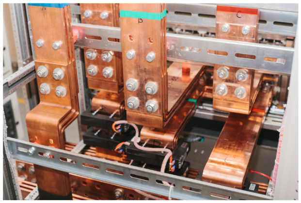
An electrical busbar refers to a metallic strip that facilitates the connection between incoming and outgoing electrical feeders. Moreover, busbars serve as a junction point in any electrical distribution network. Typically, high-conductive metals and alloys such as Aluminum 6061, Copper C11000 and C19400, and Brass are common in the manufacture of busbars.
In large current applications, joining feeders by twisting causes overheating, hence, leading to circuit failure. Therefore, such connections are replaced with busbars as they provide sufficient surface area for heat dissipation. However, busbars are also applicable for low-current applications like lighting and household panels. Furthermore, the list below highlights the general features of busbars:
- Shape: Flat strip, solid bar, hollow cylinder, or a custom design depending on specific requirements.
- Connection/Terminal: Plug-in, terminal block, bolted, clamped, or even welded in heavy applications.
- Insulation: Insulating sleeves, epoxy coatings, or encapsulation prevent electrical contact with other components as well as grounded parts.
- Applications: Power distribution systems, especially switchgears and motor control centers.
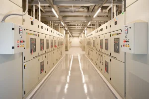
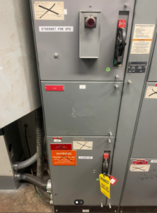
Busbar in Switchgear
Busbar is a mainstay in electrical distribution equipment such as switchgear and motor control centers. In this equipment, the temperature of the busbar rises as it conducts electricity but this increase should not be excessive. Generally, industry standards peg this at a maximum of 65℃ to avoid overheating the insulation, which reduces its lifespan. Several factors can influence the temperature rise of a busbar during operation with some of them as follows:
- Size as well as type of material of the busbar.
- Whether the busbar has insulation or not. Surprisingly, having insulation helps keep the busbar cooler due to better radiation of heat by the insulating material.
- Availability of ventilation within the enclosure.
- Size and also material of the enclosure.
- Also, proximity of other conductors and heat-producing devices.
Because the factors are numerous and not interrelated, it is difficult calculating temperature rise. Thus, applicable standards require continuous current tests to determine the temperature rise of a bus design. Also, some specifications call for busbar sizing according to current density, such as the NEC requiring 1,000 A/in2 for copper bus. Selecting a bus size this way serves for a single conductor in free air, but is not satisfactory when designing practical equipment.
How to Calculate Busbar Size
Calculating busbar sizes involves determining its cross-sectional area on the basis of current capacity, permissible temperature rise, as well as other factors. The following sections highlight key considerations when determining a minimum busbar size.
Determine the Current Rating
Identify the maximum current that the busbar will carry. Moreover, this should come as part of the specifications of the power distribution equipment that it will be in.
Select the Material
This is typically copper or aluminum. Copper has better conductivity, so it is suitable for carrying larger current capacities. While aluminum is lighter and less expensive, but requires a larger size to carry the same current as copper.
Temperature Rise
There is no straightforward way of determining this because a variety of factors influence it. However, copper busbars are less likely to overheat in comparison to aluminum due to their better conductivity. Also, smaller size conductors will overheat when carrying current that exceeds their capacity.
Calculate Cross-Sectional Area
The minimum cross-sectional area of a busbar is a function of the maximum current it will carry as well as the material current density as follows:
[Latexpage] \[ CrossSectional Area=\frac{Current}{Current Density} \]
Using this expression, the minimum cross-sectional area for a copper and aluminum busbar at 1,000 A rating will be 833.33 mm2 and 1,250 mm2. This is because copper has a 1.2 A/mm2 current density while aluminum is at 0.8 A/mm2.
Voltage Drop Consideration
The longer the busbar, the greater the voltage drop, so ensure that this remains within acceptable limits.
Mechanical Strength
Consider the mechanical strength requirement to support the busbar and also withstand physical forces, including short circuit forces.
Simulation Tools
Electrical design software tools such as ETAP and AutoCAD Electrical can provide more precise calculations and validations. This is especially useful when estimating the temperature rise, as this software can model external factors like enclosure and ventilation.
Compliance to Standards
Ensure compliance with relevant standards like IEC 61439 that provide sizing guidelines as a result of safety factors, current, etc.
Busbar Rating Chart
The busbar rating chart provides a standard way of determining busbar size due to voltage or current rating, and other factors. These charts also contain details on how many busbars need to be in the configuration. The following table highlights what a typical busbar rating chart looks like.
| WxT [mm] | Cross-section [mm2] | Weight [kg/m] | Continuous Current[A] | |||
| Alternating current up to 60Hz II | ||||||
| Tin-plated Busbars | Bare Busbars | |||||
| I | II | I | II | |||
| 15 x 3 | 44.5 | 0.396 | 187 | 316 | 162 | 282 |
| 20 x 3 | 59.5 | 0.529 | 237 | 394 | 204 | 348 |
| 25 x 3 | 74.5 | 0.663 | 287 | 470 | 245 | 412 |
| 30 x 5 | 149 | 1.33 | 447 | 760 | 379 | 672 |
| 40 x 3 | 119 | 1.06 | 435 | 692 | 366 | 600 |
| 50 x 5 | 249 | 2.22 | 697 | 1140 | 583 | 994 |
| 60 x 5 | 299 | 2.66 | 826 | 1330 | 688 | 1150 |
| 80 x 5 | 399 | 3.55 | 1070 | 1680 | 885 | 1450 |
| 100 x 5 | 499 | 4.44 | 1300 | 2010 | 1080 | 1730 |
| 120 x 10 | 1199 | 10.7 | 2110 | 3280 | 1740 | 2860 |
| 160 x 10 | 1600 | 14.2 | 2700 | 4130 | 2220 | 3590 |
| 200 x 10 | 2000 | 17.8 | 3290 | 4970 | 2690 | 4310 |
How to Wire a Busbar
As previously mentioned, the busbar is a junction of incoming & outgoing feeders. So, its wiring involves securing source and load terminals in a busbar strip with bolts, clamps, plug-ins, or whatever mechanism is available. The tooling requirements include insulated wire, terminal connectors, a screwdriver, a crimping tool, tape or other insulation, and also safety gears.
Basic Wiring Procedure
- Turn off the power source and also wear safety gear like insulation gloves and glass.
- Then, clean the busbar and mount it in the compatible panel area, away from any conductive materials, to avoid short circuits.
- Cut the wire into the right size while exposing enough bare wire to make a good connection.
- Secure terminal connectors (lugs) at the wire ends and bolt or screw them to the busbar. Also ensure that the connection makes excellent electrical contact.
- Repeat steps 2 to 4 until all network terminals are connected to the busbar.
- Also, insulate the exposed metal part of the connections using tape, coating, epoxy, or other means.
- Turn on the power source and check whether it’s working or not.